Delphis built by Doug Kennett
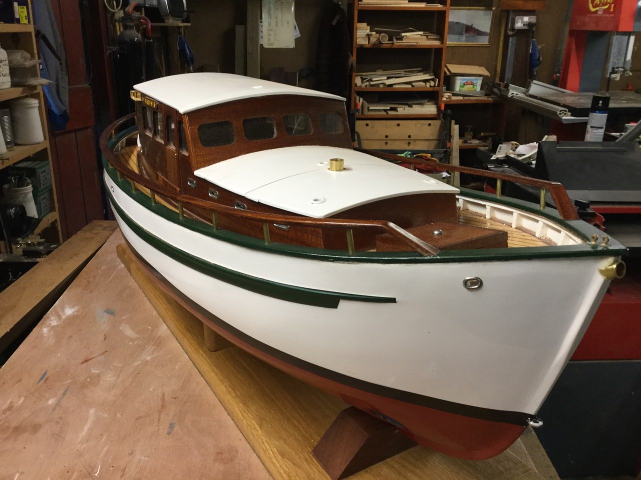
This 1050 mm scratch built model isbased on a traditionally built British registered yacht DELPHIS – a 49.25 ft motorsailer in which my wife and I sailed to the Caribbean/USA and back during 1991/2.
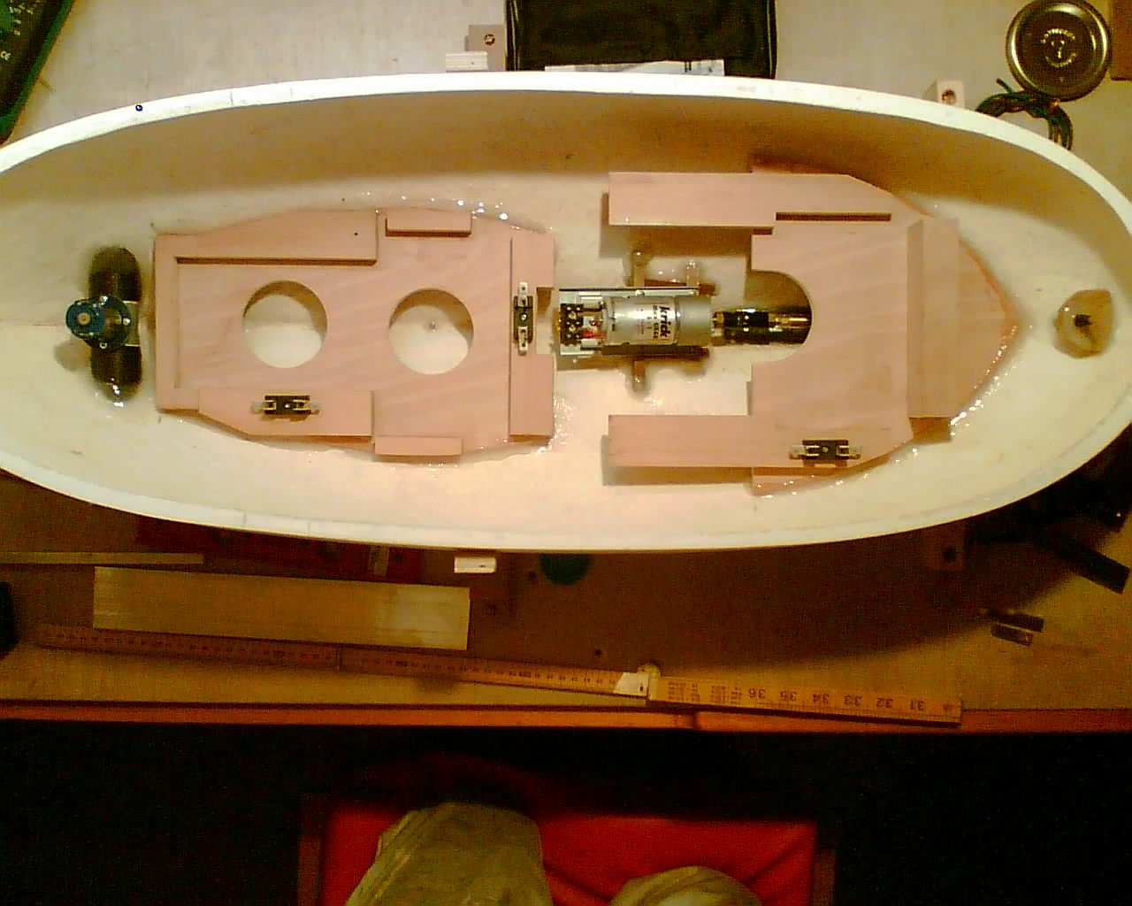
In a bath test the bare 1083 gram GRPhull required an additional weight of 8649 grams to float at thedesign water level, and a log of added weight was kept throughout thebuilding process.
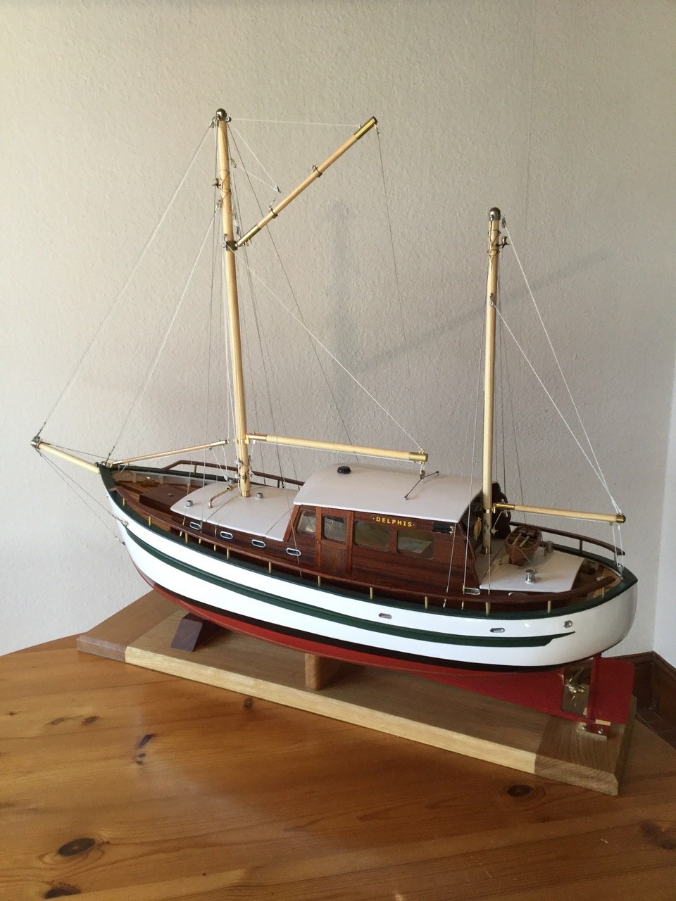
The fore and mizzen mast lights areconnected to the stainless steel standing rigging lower shrouds overbrass mast hounds, and via brass rigging screws through the deckshroud ‘plates’ to below decks.
The 30 mm diameter bow thrusterapertures in the GRP moulding were bored using a water lubricateddiamond borer in a standard drill in a reconfigured drill standmounted in a vice.
The deck and ‘caulking’ planksare laid on plywood. The fore hatch enables access to the bowthruster.

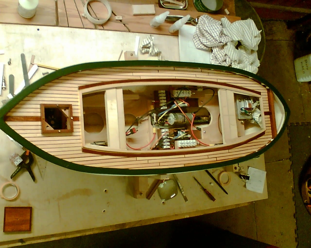
Wooden platforms were epoxied to thehull to provide mountings for batteries, control systems, and the rudder actuator servo.
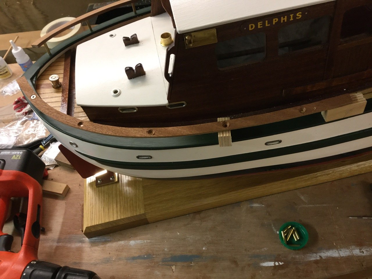
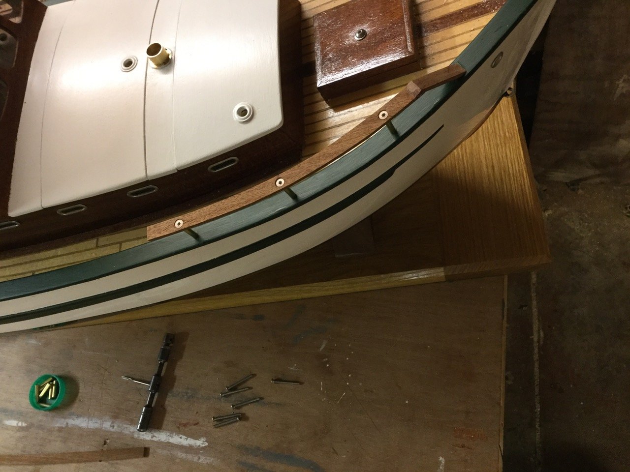
The handrail is constructed from twolayers of 2.5mm mahogany plywood. The first layer is secured bycountersunk M2 stainless machine screws passing through brass tubesprecisely cut to length, into a M2 thread tapped at the variouscorrect angles into the bulwark rail.
The second covering layer is glued into place, ensuring that no fastenings are visible, and finished with numerous coats of Superior Danish Oil.
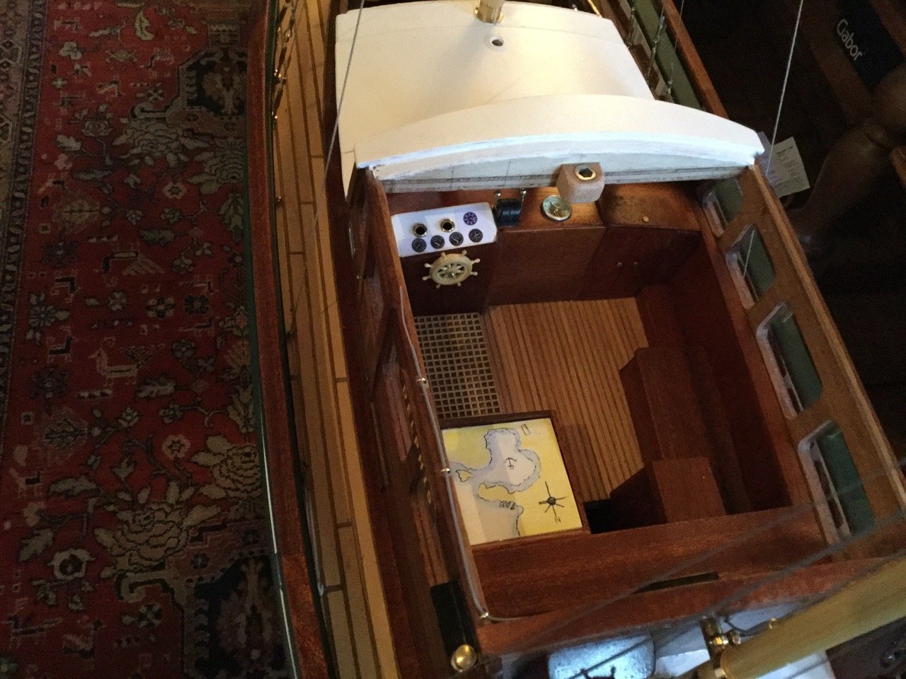
The Perspex wheelhouse windows are ‘laminated’ between the identical 4mm mahogany plywood internal and external sides. The wheelhouse interior is built on a GRP moulding and may be simply lifted in and out to give access to the batteries and electronics. Two LEDs at the instrument panel light when 12 volts and 6 volts are present at the actual input terminals of the motor and bow thruster speed controllers respectively, and 6 volts at the relay contacts for the navigation and wheelhouse lights.
KEY TO WIRING
Bow Thruster 6 volt battery
Part of 12 volt battery for motor
Part of 12 volt battery for motor
Indicator light - 12 volts supply ispresent at motor controller
Indicator light - 6 volts supply ispresent at Bow Thruster controller
800mA fuse to protect wiring for 4
800mA fuse to protect wiring for 5
Motor Electronic Speed Controller
Bow Thruster Electronic SpeedController
Relay that switches on navigationand wheelhouse lights
800mA fuse to protect wiring for 10
6 volt battery live feed (fused at13 Amps)
Switched 6 volt power to BowThruster controller
Controlled 6 volt power to BowThruster
12 volt battery live feed (fused at13 Amps at two batteries)
Switched 12 volt power to motorcontroller
Controller 12 volt power to motor
Connector blocks for indicatorlights feeds
Connector block for lighting feeds
Connector block for seriesconnection of two 6 volt batteries
Radio receiver and aerials (do notcut/shorten/reposition aerials)
Channel 1 servo output to rudder
Channel 3 servo output to motorElectronic Speed Controller